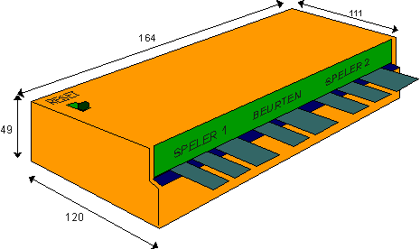
| Scoreboard | Last update 20 december 2006 |
Control box
The box consists of the following parts:
- Shift register
- CDS coder
- Signal/power separation
Control box with thumbwheel switches
Shift register
In the shift register these 32 parallel bits are converted to serial bits by importing the 32 bits at certain times with the aid of a "parallel load" (PL). This happens in the circuit with 4 x HEF4021. The bits are continuously shifted to the right with the aid of the (T) wire via the inverter. In the flow diagram signal (D) is the data stream and for example there are drawn 5 bits with equal time intervals (10010).
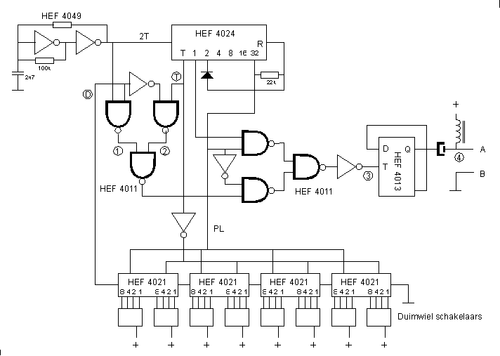
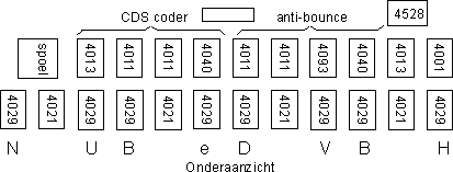
CDS coder
The left HEF4011 together with the HEF4013 form the CDS coder.
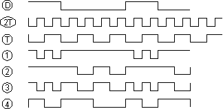 Signal (1) is formed from the combination of (D) and (2T) in the NAND gate. Signal (2) arises from (D)invert and (T). During the whole 32 bits period output 32 of the HEF4024 is low so that a NAND gate of the right HEF4011 is closed. Because of this one can think of signal (3) built up from (1) and (2). (The right HEF4011 is only way through.) In the HEF4013 signal (3) is divided by 2 and arises the CDS signal (4).
One sees direct the singularity of the cds code:
- A '1' in the data stream gives a change in the cds code.
- A '0' in the data stream gives no change.
- In the average the cds signal is low or high during the same time, this means: no DC contents.
- In any case there is a change in the cds code at every bit transition of the input signal. This means that the clock is present in the cds signal.
The frequency of the oscillator (2T) amounts about 10 kiloHertz, so that the clock for the serial data is about 5 kHz. The refreshing frequency of the parallelbits then is about 5000/32= approx. 150 Hertz.
Separation of the signal and the supply
The cross-over filter consists serial capacitor and a coil. The data signal an the supply travel together over a 2-wire connection between control box and scoreboard. The supply is meant for the control box and the data stream just goes the other direction to scoreboard. There is no distorsion if the capacitor has satisfactorily capacitance (abt. 1uF) and the coil enough self-inductance (abt.1uH). The control box consumes not much current, so the coil may have thin wire.Wiring
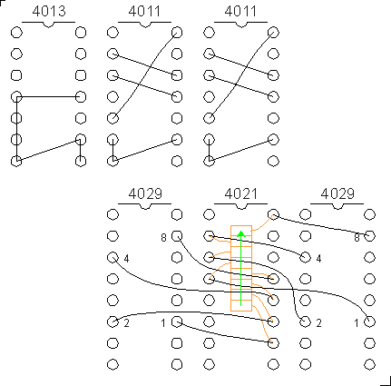 Example of wiring of a part of the transmitter print. Eventual transformer wire of 0.3 mm. can be used. The insulation of modern transformerwire melts with a hot soldering iron so that is not necessary to strip.

Control box, the one with thumb wheel switches.
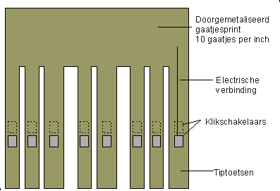
Control box with push bars
Control box with push bars. The box contains bars sawed from glass fiber circuit board. In the board there has been sawed 8 fingers: 3 for the first player, 2 for the inning and 3 for the second player.

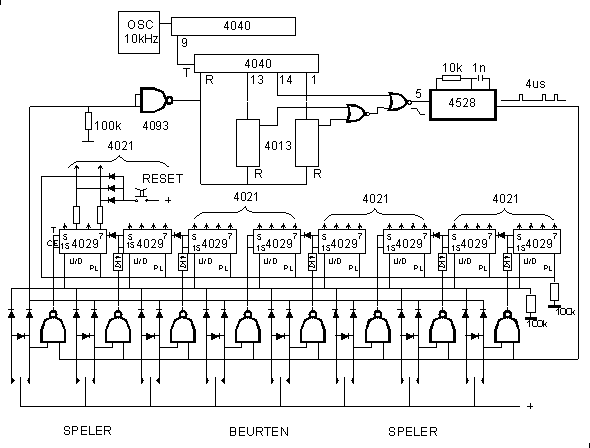
For every element (total 8) in the display there exists a HEF4029, this is an up/down counter. The diodes between the HEF4029 are needed for the carry.
The 10 kHz. oscillator and the 4040 divider is combined with the cds decoder.
The reset switch reads in all zeroes via the PL wire, so that all 4029's are set to zero except the most left HEF4029 is set to BCD 1010, this is decimal "10". This is the first -not used- code. The first 10 codes (0 to 9 incl.) are used for the figures 0 to 9 incl. With the "10" the text: "HBV DE BUN" is displayed.
Parts view of the transmitter with push bars
The characters "HBV DE BUN" at the bottom are not generated in the HEF4029's but but only serve as an aid to determine the right 4029.
Test circuit
With the test circuit a control box can be tested seperated from the main display. For the coil u can use for example a primary winding of a small 220 V. transformer.When an external sync. connection is used, this must be connected to the Parallel Load in the box.


Output signal of the control box. There are two sync. pulses, one positive and one negative.