| Scoreboard | Last update 10 august 2001 |
On august 12, 2007 i noticed on forums.azbilliards.com that there was paid attention to this site and there was a need for an english translation. I have started the translation, but, while i am a dutch-speaking person, my translation may not correct. Are there people who want to help to correct (parts of) this site, please react at the bottom.
Scoreboard for the carom billiards association
 Front view
Around 1983 i have made two scoreboards for the Billiards association 'De Bun' at Huizen (in the Netherlands). I had some annotations and it seemed to me useful to publish these on the internet for possible builders.
Block diagram
A scoreboard consists of a display and a control box, connected via a twin wire. This wire serves supply and control as well. The dimensions of the display are: width 104 cm., height 76 cm. and depth 13 cm.
Short technical description
- The scoreboard consists of a control box and a display.
- Imported (manual) data on the control box should be displayed on the display unit.
For this a continuous data stream flows from control box to display unit. - The control box is supplied from the display unit.
Data as well as supply are transported trough a twin wire connection as happened in the old days with uhf amplifiers on the roof. The cord is thin twin wire (for mains or loud-speaker). The distance is about 15 meter, but can be much larger if necessary.
To combine data and supply over a twin wire connection and to separate at the other end, cross-over filters are needed. Each filter consists of a coil and a capacitor. The cross-over filter is able to separate direct current from alternate current. The supply for the control box is the dc current, this must be separated from the data, which is the alternate current. Since the data also has a dc component, the data first has to be converted to a genuine alternate current. This happens with CDS coding.
The display unit contains 8 characters: 2 times 3 significant figures for the caramboles and two for the innings. Each display character consists of a matrix of 7x5 light bulbs and is controlled by 4 bits (BCD coding). So the 8 characters are controlled by 8x4 =32 bits. This packed of 32 bits is transmitted approximately 120 times per second from the control box. The packets are separated by synchronisation pulses. These are intervals in which the signal does not change during 2 bits. The schmitt-trigger circuit at the receiver side generates a signal if there exists such a period of 2 bits. This signal is the latch pulse for the shift register in the receiver.
The length of all bits in the data packed is shorter than the sync. pulse and the time-constant of the Schmitt trigger is longer than the longest databit and shorter than the sync. pulse. If the longest databit has a length of 1 and the sync. pulse 2, then the time constant of the Schmitt trigger lies somewhere 1 and 2, this is not critical and works with much longer datapackets than 32.
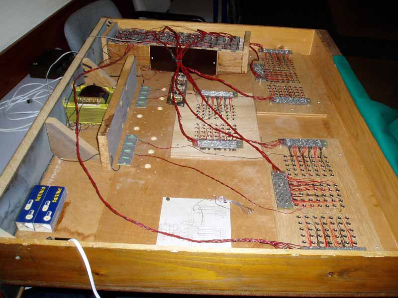
In the display unit the cds code is decoded to serial data and in a shift register converted to BCD code (8 times 4 wires). Via a switching transistor, relais-matrix and diode-matrix the display bulbs are controlled.
General remarks
When constructing this board an oscilloscope is necessary to watch the several signal shapes.