| Back |
|---|
| Scoreboard | Last update 23 december 2001 |
Receiver
The receiver consists of the following parts:
- Signal/supply combination
- CDS decoder
- Shift register
Signal/supply combination
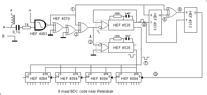
This consists of a lf choke and a capacitor. This puts supply on the twin wire for the control box and separates this dc voltage from the input of the receiver. The choke must have at least 1 henry to distort the signal not to much.CDS decoder
This consists of the upper part of the schematic diagram. The goal of the cds decoder is to recover the clock and to decode the cds signal to series data.
| Back |
|---|
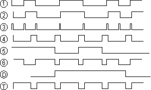 The two exclusive or's (4070) delay the signal a small bit, so that this arrives at the third exclusive or in different times. Therefore at the slopes the signals have different polarity. The exclusive or produces a '1' with different input signals so that the pulse shape (3) arises in the flow diagram.
The upper one-shot multivibrator (4528) has been wired as non-retriggerable by the feed back from output to input. With the capacitor and the resistor the time constant is set to approximately tree quarters of the time of a data bit. If there exits a second trigger pulse in this time, the one shot is not able to trigger again and arises the signal (4), this is the recovered clock. This clock now is synchronized with the clock in the control box.
The fourth exclusive or, at the right of the schematic, takes care of the right polarity of the data signal. Finally signal (D) arises, this is serial data.
The shift register
The bottom one-shot multivibrator (4528), is in contrast with the upper, retriggerable. Therefore, during the total data stream of 32 bits, the output remains active. Except, during the synchronization pulse, which is longer than 1 bit, the one shot is able to come to rest, trough which arises the strobe pulse, which shifts in the shift register the parallelbits to the 32 wires at the right moment.There is an extra circuit which activates the sentence "HBV DE BUN" on the display when the BCD code 1010 is present at one of the two HEF4021's. This is the case during reset. See also: The controlbox with push bars.