| Back |
|---|
| Scoreboard | Last update 21 december 2001 |
Path of the signal
In the scoreboard the path is as follows:
The signal for the cds decoder enters via the series capacitor. The cds decoder decodes the cds signal to normal s eries-data. This signal contains 32 bits and a synchronizing bit. The 32 bits consist of 8 x 4 bits. There are eight (3+3+2) characters in the display unit and every character is controlled by 4 bits.
This is called BCD code.
For example the figure '7': this is bcd code 0111, so 0x8+1x4+1x2+1x1=7. BCD code has 16 combinations (2 to the power of 4). Since there are only 10 combination used in the figures (0-9), the remaining 6 combinations can possible be used for text.
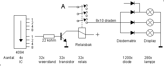
The signal passes successively the following parts:
| Nr. | Count | Description |
|---|---|---|
| 1 | 4 | ic circuit 4094, this is a series to parallel converter for 8 bits. So for 32 bits there are 4 needed. |
| 2 | 8x4 | Resistor 22 k., current limit. |
| 3 | 8x4 | Transistor for signal control. Amplifies from abt. 1 mAmp. to 30 mAmp. |
| 4 | 8x4 | telephone relais with diode. A relais amplifies from approx. 30 mA. to 1 Ampère. |
| 5 | 8x150 | Switching diodes 100 mA. |
| 6 | 8x35 | light bulbs (in my case 18V., 100 mA.) 1 display character has 7x5=35 light bulbs. |

If the light bulbs are 18V/100mA, an ac tension of 18 Volt can be applied to point A. The bulbs are on during the half period via the switching diodes. It is not necessary that the bulbs are on at full strength, this is too bright. Besides it extends lifetime. The bulbs in this board are still working from 1983, most days in the afternoon and evening!
The 32 telephone relais have a dual goal:
- Code BCD code to 1 out of 10,
- amplification from 30 mA. to 1 Amp.